Quality Control in Additive Manufacturing: SLM/LPBF Best Practices
Key Takeaways
- Additive manufacturing requires fundamentally different QC approaches than traditional manufacturing
- Every print parameter (laser power, scan speed, layer thickness) affects final part quality
- Post-processing steps (HIP, heat treatment, machining) need their own quality checkpoints
- CT scanning and non-destructive testing are essential for critical AM parts
- Digital traceability from powder lot to finished part is non-negotiable for aerospace/medical
- MES systems designed for AM can automate parameter recording and quality documentation
Metal additive manufacturing—specifically Selective Laser Melting (SLM) and Laser Powder Bed Fusion (LPBF)—has moved beyond prototyping into series production of flight-critical aerospace components, medical implants, and high-performance industrial parts. But with this transition comes a fundamental challenge: how do you ensure consistent quality when your manufacturing process involves melting metal powder layer by layer, with hundreds of variables influencing the final result?
Traditional quality control approaches designed for subtractive manufacturing do not translate directly to additive. The physics are different, the failure modes are different, and the inspection requirements are different. This guide covers the essential quality control practices for SLM/LPBF production, from incoming powder to shipped parts, and explains how a purpose-built MES and QMS can make the difference between reliable production and expensive scrap.
Why Quality Control in Additive Manufacturing Is Different
In conventional machining, you start with a known material form—bar stock, plate, or forging—with well-characterized mechanical properties. The machining process removes material but does not fundamentally alter the material's microstructure. Quality control focuses primarily on dimensional accuracy and surface finish.
In SLM/LPBF, you are creating the material and the geometry simultaneously. Each layer of powder is selectively melted by a laser, solidifying into a fully dense metal part. The resulting microstructure, mechanical properties, and internal integrity depend on hundreds of interrelated parameters: laser power, scan speed, hatch spacing, layer thickness, gas flow, powder condition, build plate temperature, and more.
This means quality control in additive manufacturing must address:
- Material creation: You are manufacturing the material itself, not just shaping it.
- Process sensitivity: Small changes in parameters can cause porosity, cracking, residual stress, or microstructural defects that are invisible from the outside.
- Internal defects: Unlike machining, AM parts can contain internal voids, lack-of-fusion defects, and trapped gas that require specialized inspection methods.
- Anisotropy: Mechanical properties can vary depending on build orientation, a phenomenon that does not exist in wrought materials.
- Post-processing dependence: As-built parts typically require stress relief, HIP, machining, and surface treatment before they meet final specifications.
Powder Management and Control
Metal powder is the raw material for LPBF, and its quality directly determines part quality. Powder management is the foundation of any additive manufacturing quality system.
Incoming Powder Inspection
Every new powder lot should be inspected before it enters production. Critical incoming inspections include:
- Chemical composition: Verify against the alloy specification (e.g., AMS 5662 for Inconel 718, AMS 4999 for Ti-6Al-4V) using ICP-OES or XRF analysis.
- Particle size distribution (PSD): Measure using laser diffraction. Typical LPBF powders target 15–45 μm or 20–63 μm distributions. Deviations affect powder bed density and melt behavior.
- Morphology: SEM imaging to verify spherical particle shape. Irregular, satellite-rich, or agglomerated powder flows poorly and creates inconsistent powder beds.
- Flowability: Hall flow testing (ASTM B213) or revolution powder analysis to ensure consistent powder spreading.
- Moisture content: Particularly critical for aluminum and titanium alloys, where moisture causes porosity and hydrogen embrittlement.
Powder Reuse and Lifecycle Tracking
One of the economic advantages of LPBF is that unfused powder can be recovered and reused. However, each reuse cycle alters the powder: particles oxidize, agglomerate, develop satellites from spatter, and shift in particle size distribution. Uncontrolled powder reuse is one of the most common root causes of quality issues in additive manufacturing.
A robust powder management system must track:
- Virgin powder lot numbers and certifications
- Number of reuse cycles for each powder batch
- Blending ratios when mixing virgin and recycled powder
- Sieving records (mesh size, sieve condition, throughput)
- Storage conditions (humidity, temperature, inert atmosphere)
- Periodic re-testing of recycled powder properties
This level of powder traceability is essential for regulatory compliance and for investigating quality deviations. You must be able to answer the question: "What powder was used in this build, how many times had it been recycled, and when was it last tested?"
Build Parameter Control and Qualification
LPBF process parameters determine the energy input to the powder bed, which in turn determines density, microstructure, and mechanical properties. Parameter control is arguably the most critical element of additive manufacturing quality.
Critical Build Parameters
| Parameter | Effect on Quality | Typical Control Method |
|---|---|---|
| Laser power | Melt pool size, penetration depth, porosity | Machine calibration, power meter verification |
| Scan speed | Energy density, balling, lack of fusion | Parameter set locking, recipe management |
| Hatch spacing | Overlap between scan tracks, density | Fixed in qualified parameter set |
| Layer thickness | Resolution, build rate, fusion quality | Recoater calibration, thickness verification |
| Scan strategy | Residual stress, distortion, surface finish | Qualified per geometry/material combination |
| Gas flow rate/pattern | Spatter removal, oxidation, consistency | Flow sensor monitoring, filter condition tracking |
| Build plate temperature | Residual stress, warping, cracking | Thermocouple monitoring, pre-heat verification |
| Oxygen level | Oxidation, porosity (especially Ti, Al alloys) | O2 sensor monitoring, threshold alarms |
Parameter Set Qualification
Before any parameter set enters production, it must be formally qualified. This typically involves building test specimens (density cubes, tensile bars, fatigue specimens) using the candidate parameters, evaluating their density (Archimedes method or CT scan), microstructure (metallography), and mechanical properties (tensile, fatigue, hardness), and documenting the results in a qualification report that forms the baseline for production.
Once qualified, parameter sets must be locked and version-controlled. Any change—no matter how small—requires re-qualification. This is a fundamental principle that many additive manufacturers learn the hard way.
In-Process Monitoring
Modern LPBF machines increasingly offer in-process monitoring capabilities:
- Melt pool monitoring: Photodiode or camera systems that detect anomalies in melt pool intensity and size, indicating potential defects.
- Layer imaging: Cameras that photograph each powder layer and each fused layer, enabling post-build review of any suspected anomalies.
- Thermal imaging: Infrared cameras that map temperature distribution across the build area, identifying hot spots or cooling anomalies.
- Recoater monitoring: Systems that detect powder spreading issues, short feeds, or debris on the build surface.
This monitoring data is enormously valuable but also enormously large—a single build can generate terabytes of sensor data. A manufacturing execution system that can link this data to specific parts and build records is essential for making it actionable rather than just archived.
Post-Processing Quality Control
As-built LPBF parts almost never go directly to the customer. A series of post-processing steps transforms the as-built part into a finished component, and each step requires its own quality controls.
Stress Relief and Heat Treatment
LPBF parts contain significant residual stress from the rapid heating and cooling inherent to the process. Stress relief is typically the first post-processing step, performed before removing parts from the build plate to prevent distortion.
Quality controls include:
- Furnace temperature uniformity surveys (per AMS 2750)
- Thermocouple monitoring with recorded time-temperature profiles
- Atmosphere control (vacuum or inert gas for reactive alloys)
- Documented heat treatment recipes per material specification
Hot Isostatic Pressing (HIP)
HIP applies high temperature and high isostatic pressure (typically 100–200 MPa in argon) to close internal porosity and improve mechanical properties. For critical applications—aerospace structural components, medical implants—HIP is often mandatory.
Key quality controls for HIP:
- Verification of HIP cycle parameters (temperature, pressure, time)
- Post-HIP density measurement to confirm porosity closure
- Post-HIP mechanical testing to verify property improvement
- Traceability of HIP batch composition (which parts were processed together)
Machining and Surface Finishing
Critical surfaces, interfaces, and threaded features typically require CNC machining to achieve the required dimensional tolerance and surface finish. Support structure removal, either manual or machined, also falls into this category.
Quality controls include:
- CMM (Coordinate Measuring Machine) inspection of critical dimensions
- Surface roughness measurement (Ra, Rz) on functional surfaces
- Visual inspection for machining defects, tool marks, or exposed sub-surface porosity
- Verification that machining has not compromised wall thickness minimums
Surface Treatment
Depending on the application, parts may undergo shot peening (to improve fatigue life), chemical passivation (for corrosion resistance), anodizing, or coating. Each treatment has its own process controls and inspection requirements.
Dimensional Control and Inspection
LPBF parts are subject to dimensional variations from thermal distortion, support strategy, build orientation, and post-processing. A comprehensive dimensional control strategy includes:
First Article Inspection (FAI)
The first production part from a new design or after any process change must undergo complete dimensional inspection. For aerospace, this follows AS9102 requirements: every dimension, tolerance, and note on the engineering drawing is measured and recorded in a formal FAI report. This becomes the baseline for all subsequent production.
In-Process Dimensional Checks
Rather than waiting until final inspection to discover dimensional issues, integrate dimensional checks at key stages:
- Post-build, pre-machining: 3D scanning or CMM measurement of as-built geometry to verify adequate stock allowance for machining.
- Post-stress-relief: Check for distortion that may have occurred during thermal processing.
- Post-machining: CMM inspection of all critical dimensions and GD&T features.
CT Scanning for Internal Integrity
Computed Tomography (CT) scanning is increasingly used for LPBF parts to detect internal porosity, inclusions, and lack-of-fusion defects that are invisible to external inspection. For critical applications, CT is often a mandatory inspection step, with acceptance criteria defined for maximum void size, void density, and void location relative to high-stress features.
Flow Testing and Functional Verification
Many LPBF applications involve internal channels, conformal cooling passages, or fluid flow paths that cannot be inspected visually or dimensionally. Flow testing verifies that internal passages are clear, correctly dimensioned, and free from trapped powder or partial blockages.
Common flow test methods include:
- Air flow testing: Measuring air flow rate at a specified pressure differential to verify passage cross-section.
- Hydrostatic pressure testing: Pressurizing internal passages to verify leak-tightness and structural integrity.
- Dye penetrant testing: For surface-breaking defects on internal and external surfaces.
Flow test results must be recorded and linked to the specific part serial number as part of the traceability record.
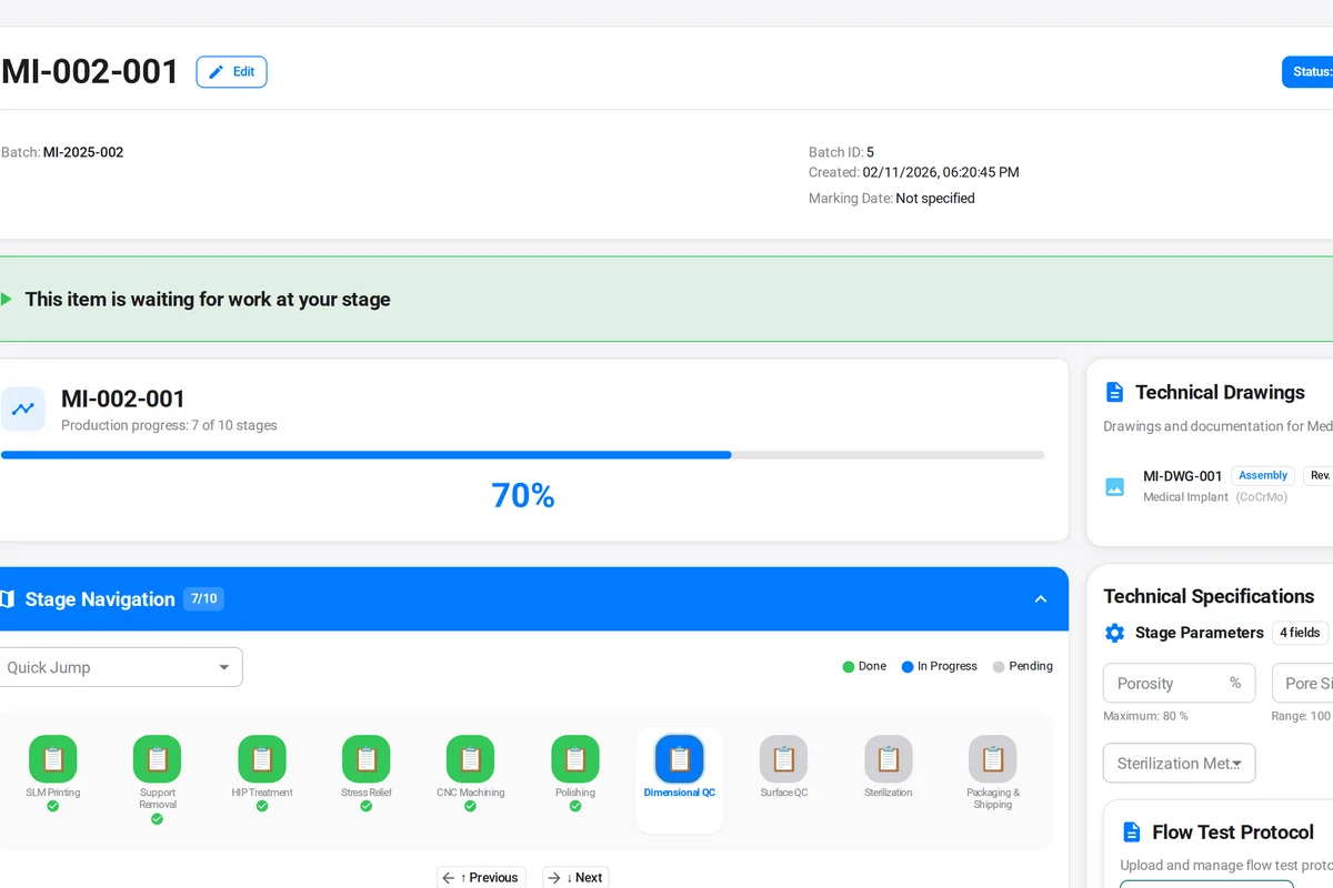
How MES/QMS Enables Additive Manufacturing Quality
The complexity of additive manufacturing quality control creates a data management challenge that manual systems cannot handle. Consider what needs to be tracked for a single LPBF part:
- Powder lot, reuse cycle count, and test results
- Build file version, parameter set version, machine ID
- Build log data (O2 levels, chamber temperature, build time)
- In-process monitoring data and anomaly flags
- Stress relief furnace chart and recipe
- HIP cycle parameters and batch record
- Machining program, machine, and operator
- CMM inspection data for each operation
- Surface treatment records
- CT scan results
- Flow test results
- Final inspection sign-off and certificate of conformance
Multiply this by hundreds or thousands of parts per month, and the need for a digital system becomes undeniable. A purpose-built MES with integrated quality management provides:
- Automated traceability: Every data point is automatically linked to the part serial number, build ID, and work order.
- Process enforcement: Operators cannot skip inspection steps or proceed without recording required data.
- Powder lifecycle management: Digital tracking of powder batches from receipt through every reuse cycle.
- Parameter version control: Build parameter sets are locked, version-controlled, and linked to each build job.
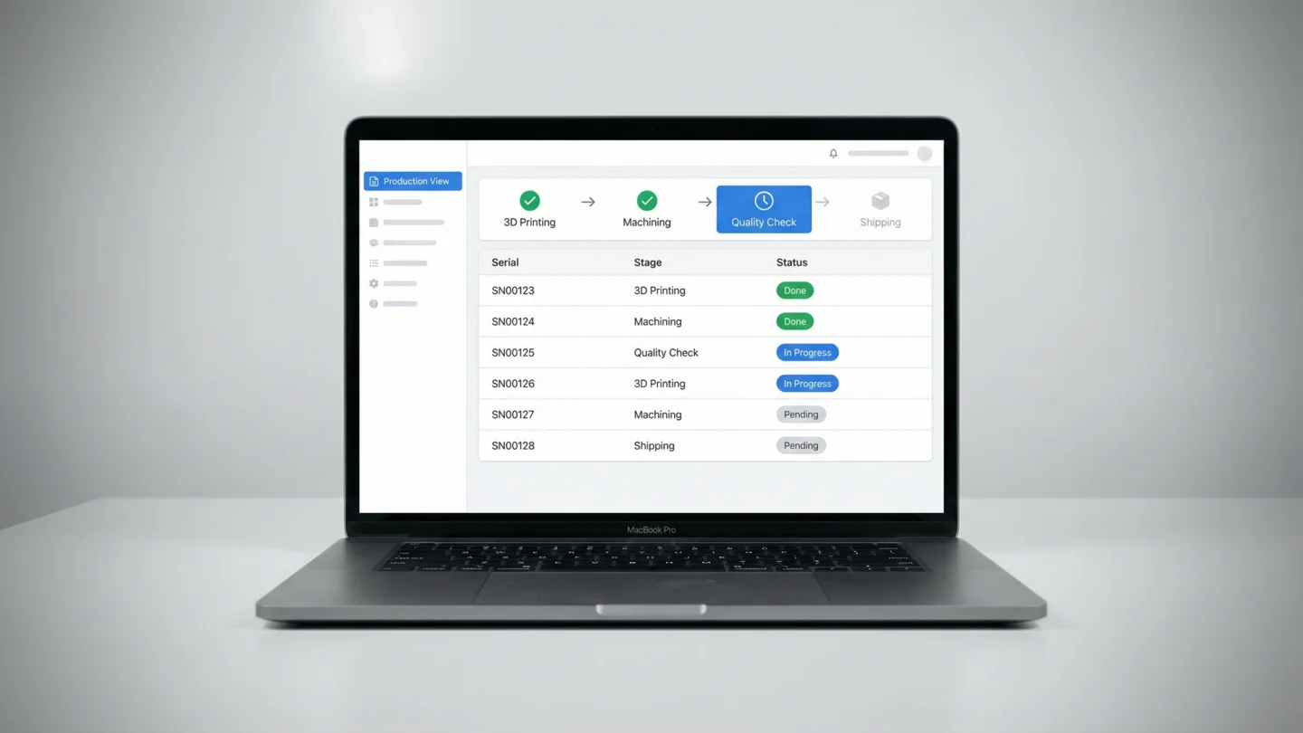
- Real-time visibility: Production managers can see the status of every part, every build, and every quality hold in real time.
- Automated documentation: Certificates of conformance, first article inspection reports, and traceability packages are generated automatically from production data.
ProductFlow: Built for Additive Manufacturing
ProductFlow is purpose-built for additive manufacturing quality control. Track powder lifecycles, enforce build parameters, manage post-processing workflows, and generate compliance documentation automatically. See pricing or discover how ProductFlow works.
Building a Quality Culture in Additive Manufacturing
Technology alone does not guarantee quality. The most successful additive manufacturing operations combine robust systems with a quality-first culture:
Invest in training: LPBF operators need to understand not just how to run the machine, but why each quality control step matters. When operators understand that a skipped oxygen reading could result in a cracked turbine blade, compliance follows naturally.
Standardize everything: Written procedures for every process step, from powder handling to part shipping. Standardization reduces variability and makes training new team members faster.
Learn from every build: Conduct post-build reviews, especially for builds with anomalies. Share findings across the team. Maintain a lessons-learned database that becomes institutional knowledge.
Engage with standards bodies: Additive manufacturing standards (ASTM F3122, F3301, F3302, ISO/ASTM 52901, 52904, 52920) are evolving rapidly. Stay current with industry working groups and adopt new standards proactively rather than reactively.
Key Takeaways
- Additive manufacturing quality control is fundamentally different from subtractive manufacturing because you are creating the material and the geometry simultaneously.
- Powder management—incoming inspection, reuse tracking, and lifecycle control—is the foundation of LPBF quality.
- Build parameter control requires formal qualification, version locking, and in-process monitoring to ensure repeatability.
- Post-processing (stress relief, HIP, machining, surface treatment) each introduces its own quality requirements and inspection points.
- CT scanning is increasingly essential for verifying internal integrity of LPBF parts.
- Digital MES/QMS systems are not optional for production-scale additive manufacturing—the data management complexity exceeds what manual systems can handle.
- Purpose-built tools like ProductFlow that understand additive manufacturing workflows provide a significant advantage over generic quality systems.
As additive manufacturing continues its transition from prototyping to production, the manufacturers who master quality control will be the ones who win production contracts, pass customer audits, and build reputations for reliability. The investment in quality systems, training, and technology pays for itself many times over in reduced scrap, faster qualification, and customer confidence.